
Use the glTF 2.0 Display component to define geometry that should be rendered in the online ShapeDiver viewer. The component takes two inputs: the geometry to display, and a material definition that can be created using the glTF 2.0 Material component. Materials can be either applied using the Material input of the component or by means of attributes for more fine-grained control.
Use the material input to define a default material for all input geometry
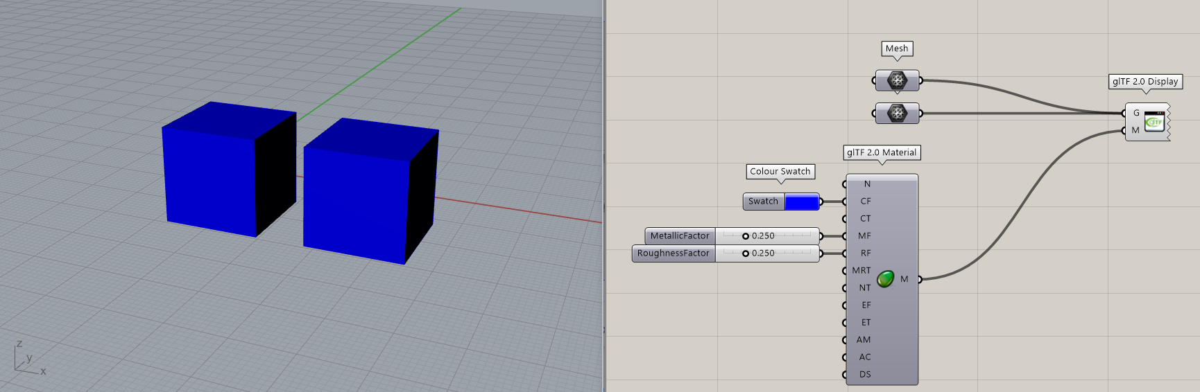
When all geometry sent to the display component shares a single material, one can simply create the material using a glTF 2.0 Material component and assign it using the material input of the component:
If several objects need different materials, it is still possible to use a single display component. One can input a data tree in the Geometry input and a list of materials in the Material input. The component exceptionally breaks the traditional access mechanism for lists and tress: instead it matches each branch of the Geometry input with an item in the materials list:
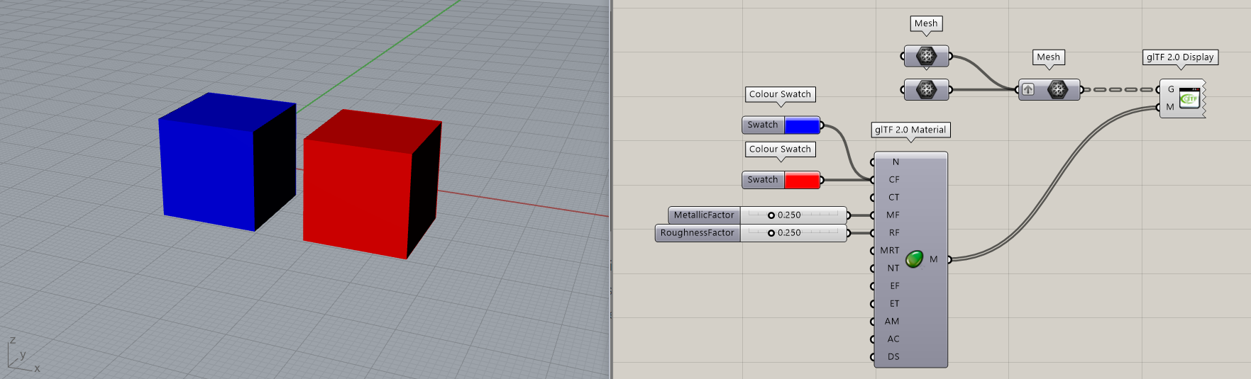
This is justified by the fact that you can apply one material to various geometries but you can not apply various materials to one geometry.
This method will only work with the set of uppermost branches of a tree. If more flexibility is needed (i.e different materials for elements in a single tree branch), then it is recommended to define materials using attributes, as described in the section below.
It is also possible to define materials using the Preset Material component. See this Note for details.
Use attributes to control the material of each input object
The component also offers a more flexible and intuitive way to apply separate materials to each piece of geometry, without having to use any complex data structure.
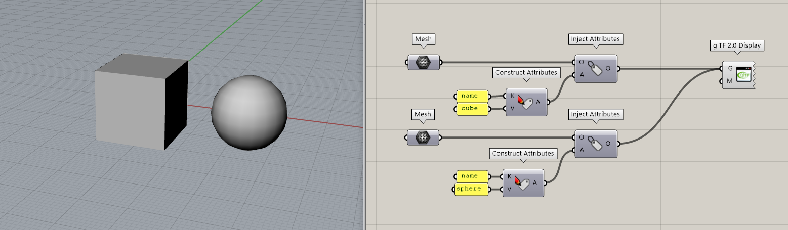
Each geometric object can be assigned a material attribute individually, using the Construct Attributes and Inject Attributes components. Construct an Attributes object using the reserved attribute name “material” and use a glTF 2.0 material as the value, and then inject this attribute in the geometry:
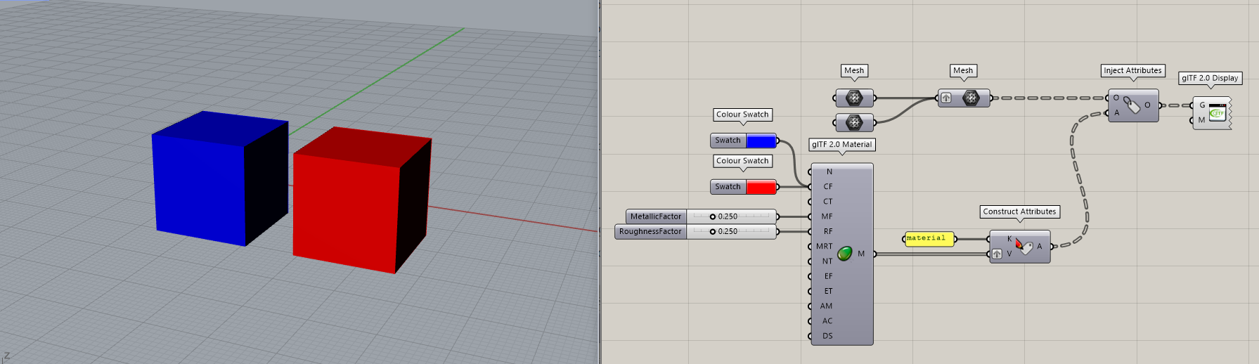
When using this method, it is not necessary to connect any material to the Material input of the Display component. However, if a material is connected, it will be used as the default for all geometric objects which do not contain a material attribute.
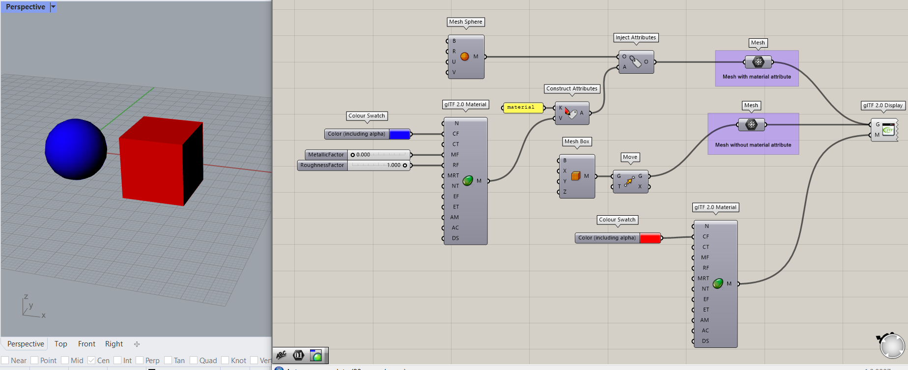
In the example below, the sphere gets a material attribute (blue material) while the cube does not get any attribute. Therefore the sphere is displayed with its assigned attribute while the cube is displayed using the fallback red material used as input of the display component.
Read more about the Attributes system here.
It is also possible to define materials using the Preset Material component. See this Note for details.
Use the transform attribute to attach transformations
If the same geometric object is reused multiple times in the final display, it is more efficient to store the object only once and attach transformations to it. That way the object will be stored in the glTF and transferred only once, and the online viewer only needs to receive the object once and read the attached transformations to display the other instances of the same object. Attach transformations using the Attach Transformations component before sending geometry to the glTF 2.0 Display component and the viewport will preview all instances of the object. Read more about attaching transformations here.
Use the name attribute to name objects and influence the scene tree
You can assign names to objects, using the Construct Attributes and Inject Attributes components. Use the reserved attribute name.
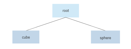
Attaching names to objects allows you to influence how the scene tree will be constructed. In the above example, the scene tree in the online viewer will look as follows:
Now consider the following example:
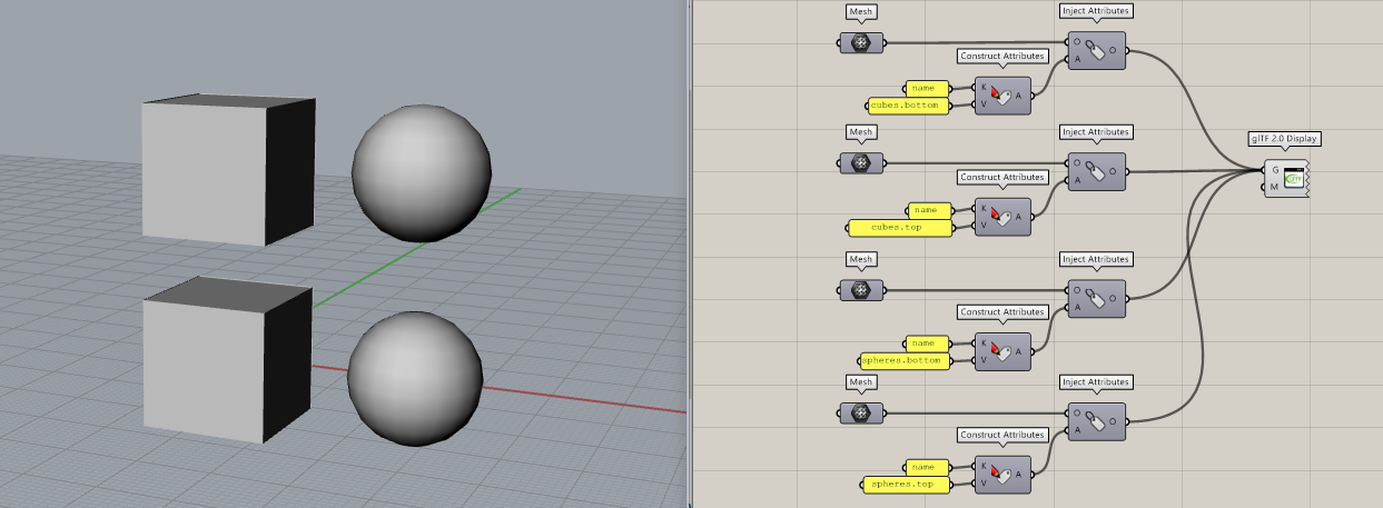
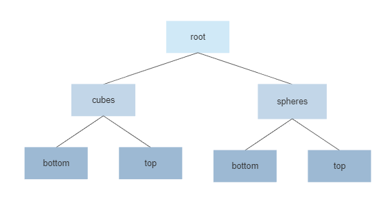
Using the point-separated notation, this model defines two branch levels for the scene tree, which will look as follows:
At the moment, controlling the scene tree is only useful when using the Viewer’s API. Each object can easily be identified in the API using the point-separated notation to identify which node of the tree it belongs to. The hierarchy also makes it much more convenient to implement interactions (such as defining entire parts of the scene tree which can be used for selecting and drag-and-dropping instead of having to define a group of unrelated objects).
In the future, the platform will include a scene tree explorer according to the scheme defined above.
See exactly how the scene tree is organized using the name attribute in the table from the section below.
Details about the generated glTF 2.0 assets
The glTF 2.0 Display component outputs a single glTF 2.0 asset which embeds the materials that were assigned to the geometric objects as explained above.
These are the processing steps applied by the glTF 2.0 Display component when generating the glTF 2.0 asset:
|
Step |
Description |
|---|---|
|
Discretize |
Surface-like objects are discretized to meshes.
|
|
Scene tree |
Using the
This will result in the following scene tree of nodes:
|
|
Group |
Objects are grouped by the type of discretized geometry, and by the transformations attached to them. This happens separately for each node of the scene tree, and allows to minimize the amount of data to be transferred. Each group is given a name depending on its transformations. Group name |
|
Split |
Objects which exceed the maximum vertex count of 65535 vertices are split into smaller objects which do not exceed this limit. This happens due to a limitation of WebGL on most graphics cards. |
|
Create nodes |
A flat list of nodes is created from the groups, separately for each node of the scene tree. Groups with transformations result in a node containing child nodes, one for each transformation. |
|
Create asset |
A glTF 2.0 asset is created from the nodes resulting from the previous step. A single top level node is used to apply a global transformation to all objects. This transformation rotates the +Z direction to the +Y direction, which is the “up” direction defined by glTF. |
Context menu options
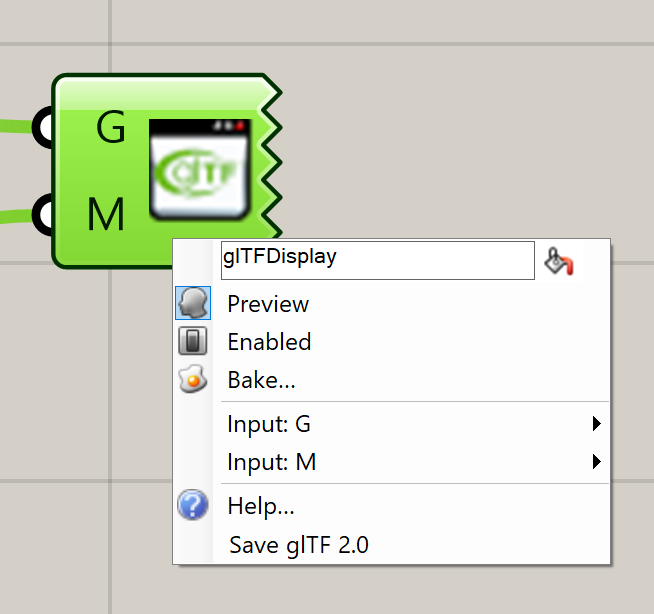
-
Save glTF 2.0: allows to export locally the glTF 2.0 asset that is generated by the component and used in the ShapeDiver online viewer. The resulting glTF asset can be used with the External Display component, loaded directly into the viewer using the glTF loader, or quickly previewed for debugging using the glTF monster.