
Using the ShapeDiver Output component, one can output enriched structured data and geometry. This comes in contrast to the ShapeDiver Display components which only produce pure visualization geometry (apart from some basic attributes used by the viewer).
On the one hand, this opens more features in the online viewer, by means of attributes:
-
Fine-grained material control
-
Define layers
-
Store custom attributes and visualize them in the viewer in attributes visualization mode
On the other hand, this opens up a completely new way to consume the geometry outputs of a ShapeDiver model, by letting users connect to a range of desktop software clients and bake the geometry outputs directly in active clients of the local machine of the user.
Below we first discuss the general properties of the component and then go through the use cases above in detail.
Background
While the ShapeDiver Display components are ideal when an application only needs to render plain geometry in the online 3D viewer, there are use cases when one might want to output geometry enriched with metadata to the web application. In order to do so, one can use the ShapeDiver attribute system and the related plugin components which allow defining and storing attributes in objects, as well as extracting said attributes back from objects in which they are stored.
Some reserved attributes are compatible with the display components (used for online rendering). However, most generic attributes (which we refer to as custom attributes) are not stored in the glTF files generated by the display components. Instead, one should use the ShapeDiver Output component.
Instead of generating a plain glTF file, the ShapeDiver Output component generates another file format which we call sdTF: Structured Data Transfer Format. This file format allows to store attributes as metadata in the objects it includes. It also retains in a lossless fashion the data structure that is fed to it (items, lists, and trees).
Check the Attributes Cheat Sheet in order to see how each reserved and custom attributes can be used in relation with various ShapeDiver features (define materials and layers, use the attribute visualization mode on the platform…).
Defining inputs of the component
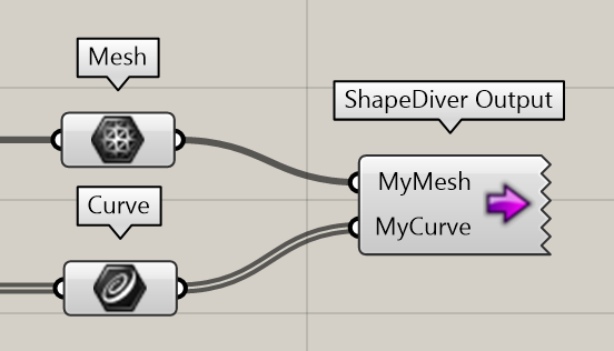
Much like the native scripting components of Grasshopper, the ShapeDiver Output component lets users define a variable number of inputs, which result in structured data in the resulting files sent to the web application:
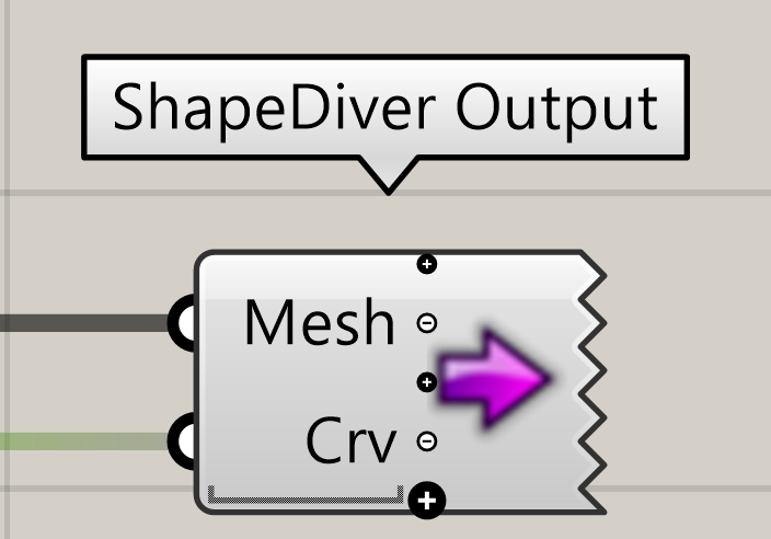
Each input of the component can only receive data of one nature (i.e. only meshes, only Breps or only numbers). For that reason, the component requires data to pass through a floating parameter component before being connected as input:
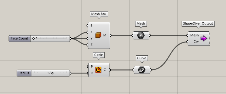
See it as a forced sanity check on the data sent to the component.
Each of the inputs of the component inherits the name of the floating parameter connected to it:
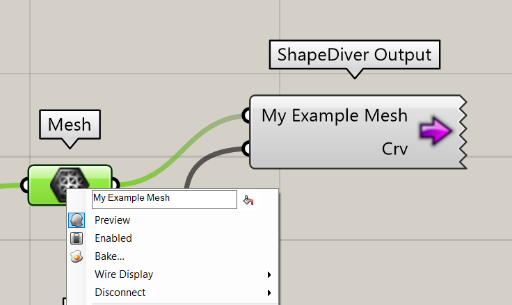
In the online platform and the API, such inputs can then be differentiated in the platform and APIs using these defined names.
Materials
The ShapeDiver Output component does not include a Material input, like the display components. Therefore, assigning a default material used by all objects sent to the component is not possible (see "Use the material input to define a default material for all input geometry").
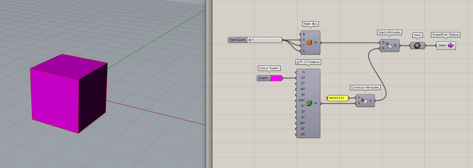
However, the second method to assign materials using attributes (see “Use attributes to control the material of each input object”) is compatible with the Output component, and such stored materials will result in fully rendered geometry in the online viewer.
Layers
Use the layer attribute in objects in order to enable the layers feature of the viewer in the model view page of the online platform. All objects with the same value for the layer attribute will be grouped in the same viewer layer, whose visibility can be turned on and off, or adjusted using an opacity slider:
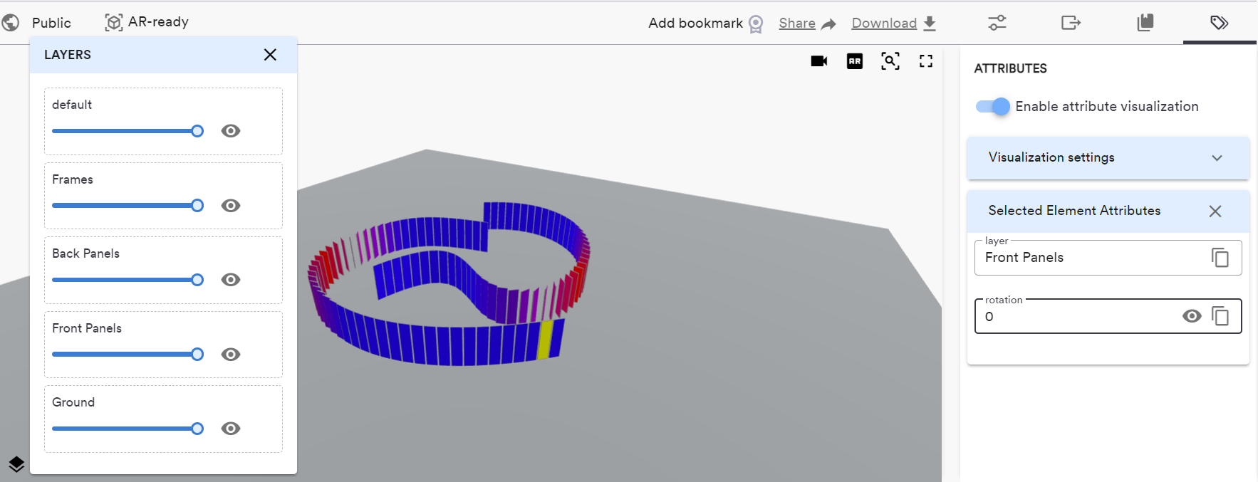
At the moment, the layers feature of the viewer is only available while in attribute visualization mode.
Usage for attribute visualization
Download the Grasshopper definition from the attribute visualization example here.
While some specific keys are related to reserved attributes, and linked to specific behavior when stored in geometry, any other key (which we refer to as custom attributes) can be used along with the attribute visualization mode of the platform. In this mode, each geometry element can be selected and its attributes displayed with their values.
Additionally, some types of attributes such as numbers, strings and colors can be used to color the individual elements contained in the model:
-
Numbers are used to define a gradient scheme spanning all values between the minimum and maximum value found in the model.
-
Strings are displayed with an individual different color for each string value.
-
Colors are displayed according to their own value.
Consider the following definition, which creates spheres with random positions and radii:
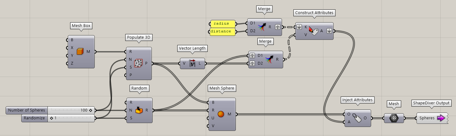
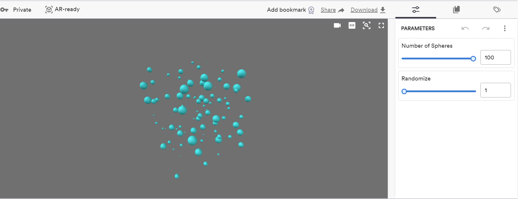
We store in each sphere two attributes, one for its radius, and one for its distance to the origin. We do not define materials, therefore after uploading the definition to the platform, all spheres get the default ShapeDiver material:
One can then switch to the attribute visualization mode (at the top of the right panel) and click on “Enable attribute visualization”. Once enabled, each of the spheres can be clicked on. The panel on the right displays both attributes that is stored in the selected sphere:
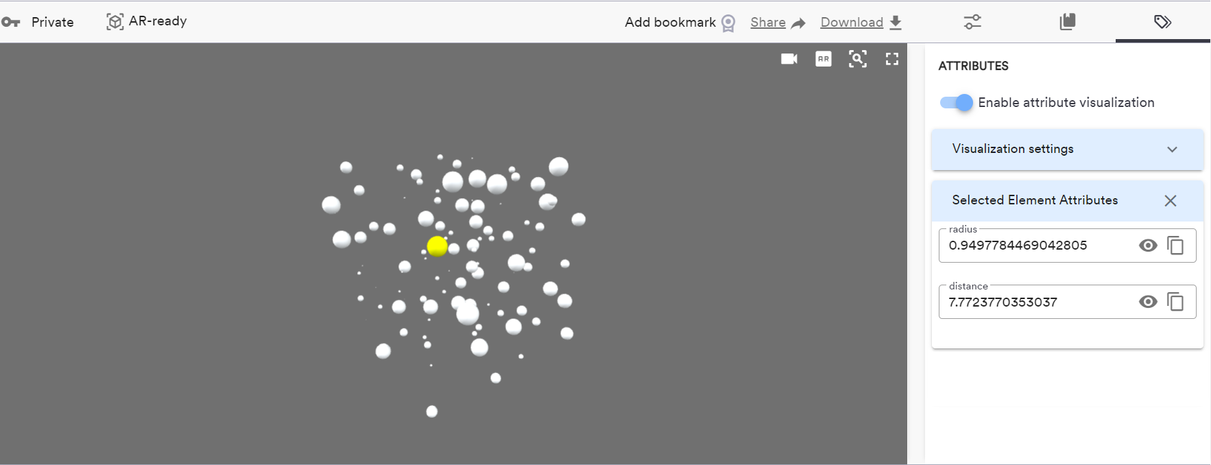
Clicking on the eye icon for a specific attribute (or manually through the visualization settings) one can then enable visualization of this specific attribute for all the objects in the scene that contain it. For example, for the radius attribute:
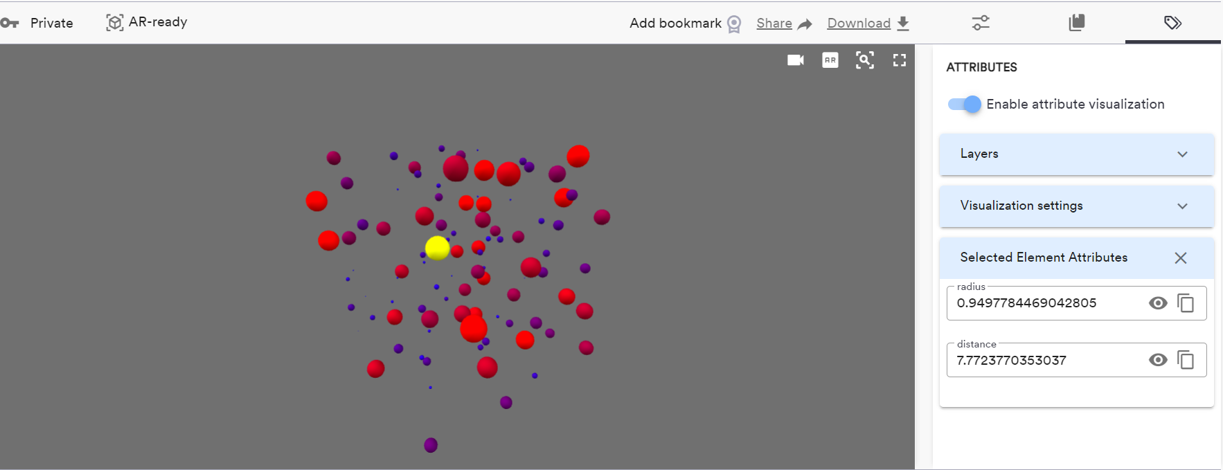
By default, a blue-red gradient is used, but this can be changed along with other settings in the “Visualization settings” section.
Read more about the attribute visualization mode on the platform.
Usage with desktop clients
Download the Grasshopper definition from the desktop client example here.
When you include a ShapeDiver Output component in a definition uploaded to ShapeDiver, its contents will be displayed in the “Exports and Outputs” panel of the model view page. Since a single component can include several streams of geometry, the UI elements corresponding to the component is an accordion which can be expanded to see the contents. Let’s take a simple example:
For this component, the corresponding expanded UI element would be as such:
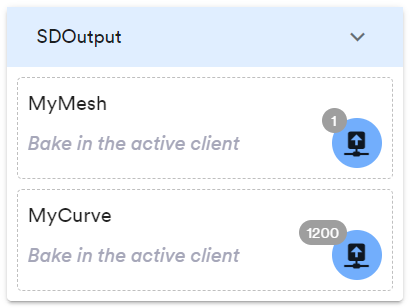
In this case, the buttons corresponding to each output are enabled and the badge shows how many objects they contain. Clicking on one of the the outputs will instantly bake it to the currently active client.
You must have enabled a connection with an active desktop client in order to enable this feature. Read more here about how to enable an active client. Depending on the status of the connection and the nature of the client, the UI might display various errors and warnings which you can read about here.
Context menu options
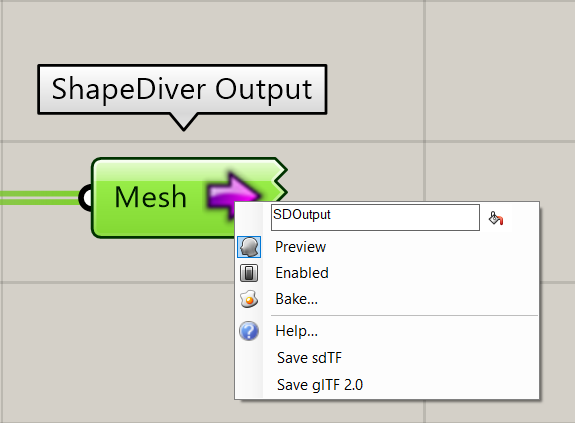
-
Save sdTF:
Documentation in progress!
-
Save glTF 2.0: allows to export locally the glTF 2.0 asset that is generated by the component and used in the ShapeDiver online viewer. The resulting glTF asset can be used with the External Display component, loaded directly into the viewer using the glTF loader, or quickly previewed for debugging using the glTF monster.